On this page
- System overview
- System makeup
- Event logging
- Mimic screen
- Shunt token
- System commands©
- MicroETS signalling interface
- DC uninterruptible power supply
- Internet security
- New developments
- Case study
System Overview
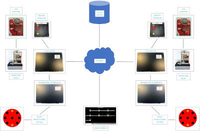
The diagram below shows the main modules of the MicroETS system
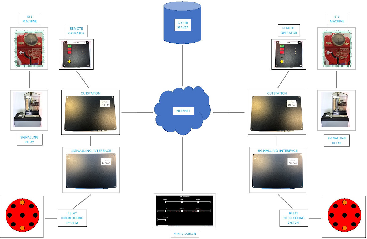
System Makeup
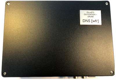
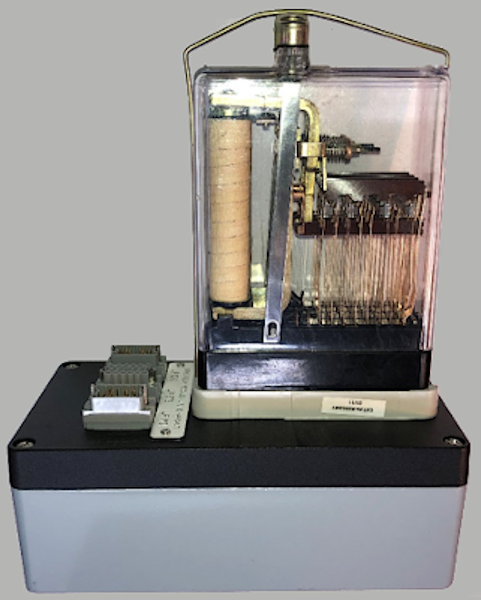
Any staff machine which uses a change of polarity to indicate a token extraction or insertion can be used with MicroETS. Each machine has a dedicated MicroETS Outstation which contains all the real-world interfacing and several MicroControllers to handle remote polarity acquisition, data logging, self-testing, configuration tasks and interfacing with the ETS machine.

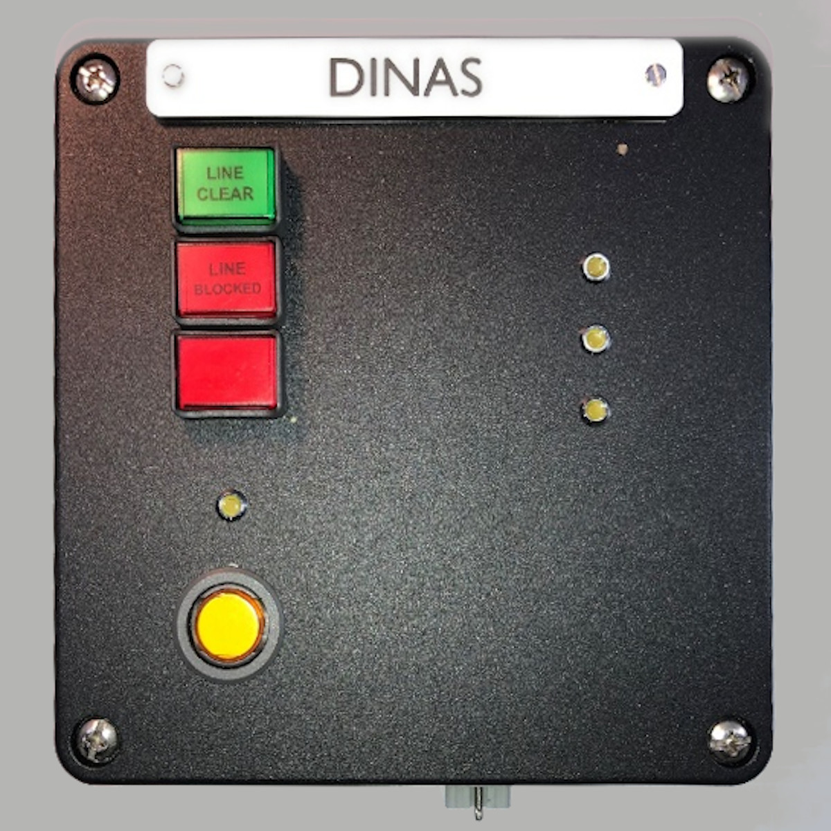
A Remote Operator module is used as the operator interface – a push button switch starts the process to acquire the polarity of the remote ETS machine. After a couple of seconds, the Remote Operator will display ‘Line Clear’ or ‘Line Blocked’. If it’s ‘Line Clear’, the BR960 Relay module will energise, unlocking the ETS machine, making a token available. The token remains on offer until one is extracted or the period of 20 seconds elapses after which the offer is withdrawn.


Event Logging
The process of extracting a token involves the remote operator button being pressed causing double-encrypted messages to be sent between the Outstations. Events such as the polarity comparison between ETS machines are stored on a local Event Recorder module in each Outstation, in plain English or alternatively, your preferred language. A cloud server is used to collect the Event Data from all the railway’s Outstations, saving that data to a cloud-based database.
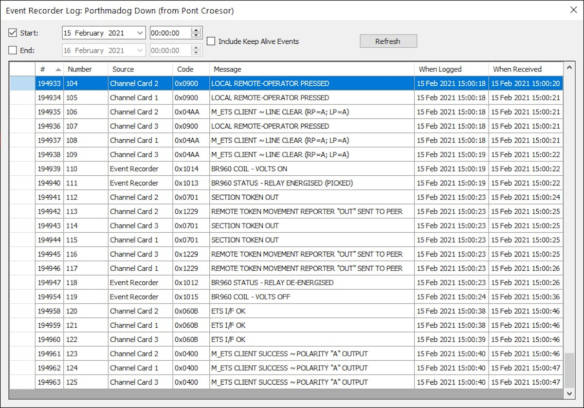
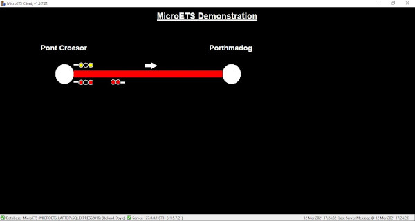
Mimic Screen
A sample of the mimic screen is shown below. Hover the mouse over the station name to get access to the drop-down menus.
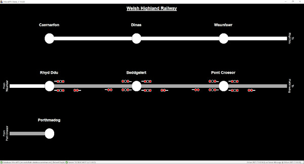
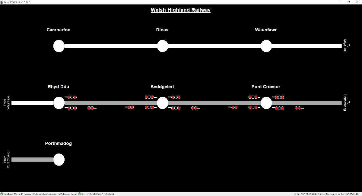
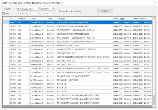
Signallers and technicians can be given access at various security levels to a Windows based program on their local PC which can interrogate the data on the cloud server. That data is used to create a MIMIC screen showing which sections are Clear, Blocked, or not yet fitted with MicroETS. The Mimic Screen contains several drop-down menus to view the Events and initiate some system commands. The following screenshot shows the events recorded for a normal token extraction.
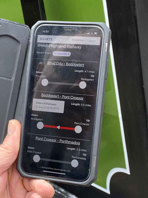
Shunt Token
The WHR has loops with Shunt tokens allowing a locomotive to run round the loop whilst an adjacent section is occupied. MicroETS will not issue a section token whilst the shunt token is out. This is represented on the mimic as shown below:

System Commands©
A MicroETS System Administrator can assign system command access rights to selected Mimic Screen operators. These are then accessed from drop-down menus on the Mimic screen.
System Command – CANCEL STARTING SIGNAL
It is also possible for a signaller to cancel a starting signal if a change of plan is necessary.
System Command – REMOTE OPERATOR GO [‘ROGO’]
Any Remote Operator can be ‘virtually’ pressed using this Mimic screen command. The chosen Outstation system will then behave as if its Remote Operator had been pressed, allowing it to be tested remotely. Twenty seconds later, the resulting events will be visible on the Mimic screen in the event log. If a token extraction had been denied, the log will contain the reason why, usually ‘Line Blocked’ or ‘Outstation Inhibited’ (see below).
System Command – REMOTE INHIBIT
On certain occasions, the railway may wish to prevent token machines from issuing tokens even though the line is clear, for security reasons. The Remote Inhibit command will do this. If a Remote Operator is pressed on a remotely inhibited Outstation, Neither the Line Clear nor Line Blocked indicators will illuminate; an LED will briefly flash meaning ‘Phone Control’.
System Command – TOKEN BALANCE
Should a token balance be needed, then this command is used to put the section into Token Balance mode. That mode will be entered if the line was clear. Normal token extractions are then inhibited and the logging of token movements is temporarily suspended. Extracting tokens through the top of the ETS machine will not cause the starting signal to be cleared. This signal can only be cleared if the token was extracted normally whilst the BR960 relay was energised.
MicroETS Signalling Interface
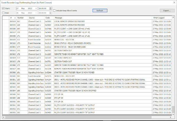
The fourth module is an optional module called the MicroETS Signalling Interface (MSI) which can automatically control starting signals directly or interface with a relay interlocking system, to give token interlocked starting signals. The Events shown below show that the three independent channels of the MSI have voted to clear the starting signal. In this case, the 3-out-of-3 voting system causes a trigger relay to pick for 5 seconds, sending a ‘Clear Starter Request’ to a Relay Interlocking system.

The MSI can be fitted with a Digital Input Card providing 12 monitoring inputs from volt-free contacts on a customer’s signalling system. These can cause events to be logged and/or a signalling element icon to change appearance on the Mimic screen. The picture below shows that the token has been removed and the right-line starting signal cleared.
In the unlikely event of a signal interlocking failure whereby, for instance, the home signal and starting signal have been cleared simultaneously, the Mimic screen can be configured to highlight the conflicting signals and sound an alarm, which can be silenced by the Mimic Screen Operator.
DC-Uninterruptable Power Supply – up time > 24 hours
The MicroETS system is powered by a purpose made DC-UPS which takes in power from the mains supply to power a 24V DC Victron Smart battery charger, which charges two Victron 12V AGM deep cycle 38 ah batteries. In the event of a mains outage, the DC-UPS will keep two MicroETS Outstations and Signalling Interfaces running for a period greater than 24 hours. The mains-fail detector and battery low detector provide alarm status outputs to each of the seven DC output sockets in the top of the unit. These outputs are fed to each Outstation and Remote Operator. The Alarm status in each case is logged by the Outstation, and visually indicated by a LED on the front of the Remote Operator. The Alarms are represented on the Mimic screen by Black Flash icons. The DC-UPS charging mode, voltage, charging history etc can be monitored without removing any covers by using the free Victron smart phone app using a blue-tooth connection. The App is password protected.
Internet Security
Messages sent between Outstations are given a magic number then obfuscated and double encrypted before transmission across a VPN. The magic number is a very large number which changes randomly each time a message is sent. When studying this system mathematically the chance of the magic number being guessed correctly is roughly equivalent to winning the UK national lottery on three consecutive Saturdays.
New Developments
A mobile phone app version of the MicroETS Mimic screen has been developed; this shows which sections are occupied, showing the direction of movement authority. The app is particularly useful for lineside workers and managers.

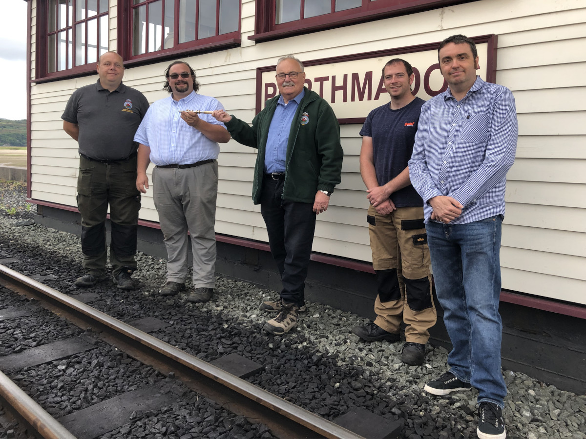
Case Study
MicroETS was developed over 16 years by two engineers who are also volunteer Drivers on the FF&WHR. Three Independent Competent Persons, all fellows of the IRSE gave expert guidance. The Ffestiniog Railway Company provided their Welsh Highland Railway as the test railway. In 2017, we refurbished 14 ex-Irish Railways S-type ETS machines for Highrail Systems Ltd. use on the WHR. Since these were mostly ‘A’ & ‘B’ pattern machines, we converted some of them to ‘C’ pattern machines to give the desired token type separation for the WHR.
In September 2021, MicroETS went live over the Southern half of the Welsh Highland railway, between Porthmadog and Rhyd Ddu, some 12 miles. The remaining 3 sections between Rhyd Ddu and Caernarfon are due to be installed in Autumn 2022. Most of the footplate crew also sign the FR route and needed no training for its use. The controllers noticed the big difference changing from Staff & Ticket to MicroETS. Now they can observe a train departing or check when it departed to assist them in planning an alternative passing place if it’s ‘one of those days’.